Evolution has provided mankind with two eyes. By doing so, only now can we see in space and thus not only recognize forms and outlines, but also estimate distances. However, what is quite natural for us, is a complex task in industrial image processing. So, how do 3D images come about exactly and which technologies help with their implementation in order to teach machines to see and think?
 Babies do not yet have a sense of how far apart their eyes are. They cannot yet tell if something is far away or very small, they only see in two-dimension. Adults, however, have spatial vision, which means they can estimate how far away an object is. This inherent triangulation is based on experience. Only experience tells us that at the back of the picture in Figure 1, the human beings are not toy figures in the girl’s hand. Classic 2D vision programs do not know this and need to work with estimates and approximations, which they learn by using sophisticated algorithms that determine the approximate 3D coordinates and distances of an object. Methods of this kind are not only expensive, but also inaccurate and limited to a certain distance. In modern automation and human-machine collaboration, accurate 3D data is indispensable for accurate, real-time measurement and interaction. The various 3D methods are now mature and often available as ready-to-use cameras and modules on the market. This article examines three of the most common technological approaches, highlighting the advantages and disadvantages for generating accurate 3D data.
Figure 1: Optical illusion in 2D shooting
Picture by Hayley Foster / Licence: CC BY-SA 3.0
Passive Stereo Vision: 2 x 2D = 3D

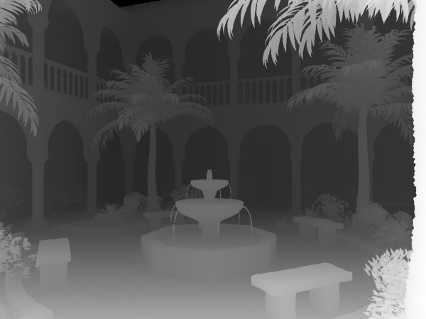
Today’s stereo vision cameras are usually available at the board or module level or as a finished product in a solid housing. The cameras are pre-calibrated, enabling 3D images and depth maps to be created for structured surfaces without much computational effort. The advantages of disparity-based triangulation techniques lie in the fact that there are no discretization levels for the distance and allowing a very high level of accuracy to be achieved. Disadvantages arise with very homogeneous textures, since the entire surface has the same appearance and the camera cannot detect any reference points.
Figure 2: In disparity maps, distances are represented by color coding
Picture by Fréderic Devernay
Active stereo vision with pattern projection
By projecting so-called patterns, active stereo-vision methods add additional information to the image using structured light to simulate non-existent textures. An inverse camera sends rays from a 2D array onto the surface, while a conventional 2D camera searches for the projected object (ie a red dot). For this purpose, the triangulation and angle measurement within the resulting geometric triangles is used, since the distance between the inverse camera and normal camera is known, calibrated and fixed. Dimensions and distances can be precisely and quickly measured without contact. The disadvantage of this active stereo vision method lies in the possible fanning of the rays at high distance. The “drifting apart” points can lead to a poorer resolution and thus to a less accurate result.

Figure 3: Disparity and depth resolution when looking from two cameras at an object
State-of-the-Art 3D Camera Modules
Novel 3D cameras and embedded vision modules, such as the Intel® RealSense ™ series, combine both active and passive stereo vision techniques, making them suitable for all types of surfaces. The Pattern projector can be turned on or off as needed and provides homogeneous textures for reference points. Regardless of an active or passive approach, the calculation of triangulation and creation of depth maps has traditionally been very computationally intensive, being mostly done on separate host PCs. Now, integrated 3D solutions have an dedicated ASIC chip installed just behind the image sensor for processing, which only handles 3D operations and provides real-time processing.
Time of Flight
The measurement principle of Time of Flight (TOF) cameras is radar-like and based on the time it takes for a laser or infrared pulse to get from the camera to the object and back. The longer the measured time, the greater the distance between the camera and the object. Transmitter and receiver modules are integrated in the TOF camera and synchronized with each other, so that the distance can be extracted and calculated. The sensor integrated in the TOF camera measures the time elapsed between emission and reflection of the light. Since each emitted pulse contains information about the time and the angle or the direction, the distance can be determined from this and outputted as a depth map. The individual pulses are coded to ensure accurate allocation and to avoid inaccuracies between shipping and receiving. The time of flight measurement is based on the speed of light and results in real-time image processing and high lateral resolution combined with depth information. Unlike laser scanners, which move and measure point by point, Time of Flight cameras measure a complete scene with one acquisition, reaching up to 100 frames per second. TOF cameras are usually available in a VGA version, and so far there are only a few available standard cameras in the megapixel range. The low resolution is the main disadvantage of this technology, because it limits the possible applications scenarios for TOF cameras. On the other hand, Time of Flight solutions are very simple and compact compared to other systems as they contain no moving parts and have built-in lighting next to the lens. Due to the simple distance information, TOF cameras consume only little processing capacity and thus little power. For more complex tasks, such as embedded vision applications and higher resolutions, integrated 3D cameras or modules rely on a combination of passive and active stereo vision.
Artificial Intelligence boosts 3D Technology
Intelligent algorithms can help improve the quality of the depth images and minimize fault tolerance when mapping and correlating image data. However, artificial intelligence has the most potential when 3D information is used within an application to intelligently automate and control processes in real time with accurate image information. Using 3D technology and image-based AI, machines can accurately analyze environments and objects and generate a new level of perception. Intelligent algorithms can use 3D to make even more accurate and faster analyzes and valid decisions. For example, on a conveyor belt for sorting packets, a neural network can learn by itself what identifies the objects and thus recognizes and classifies them in the future. Machine learning works much better with 3D because there is more information and no lengthy assumptions and estimates required. Innovative applications in industry and everyday life benefit from the combination of 3D technology and Artificial Intelligence, turning machines into intelligent partners.


